This is my first time soldering an entire circuit board.
It’s a YCA2109 electronic dice practice board. After reorienting the two ICs, the LEDs on the board finally lit up. At that moment when the lights came on, my immediate reaction was: awesome, the whole process finally worked, and I didn’t mess it up.
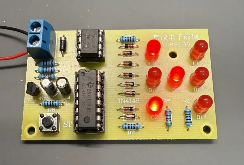
After both chips were reoriented, some of the red LEDs on the YCA2109 board lit up during a brief test.
I wanted to practice soldering and also end up with something usable
The most direct reason I chose this practice board in the first place was that I wanted to practice soldering.
But I didn’t just want to practice a few isolated solder joints over and over. I wanted to finish with something complete on my desk: a board with a button and lights that could run when powered on. So I chose the electronic dice kit.
When it first arrived, it didn’t look like a product—just an empty PCB, a parts list, and a bag of components I could barely tell apart.
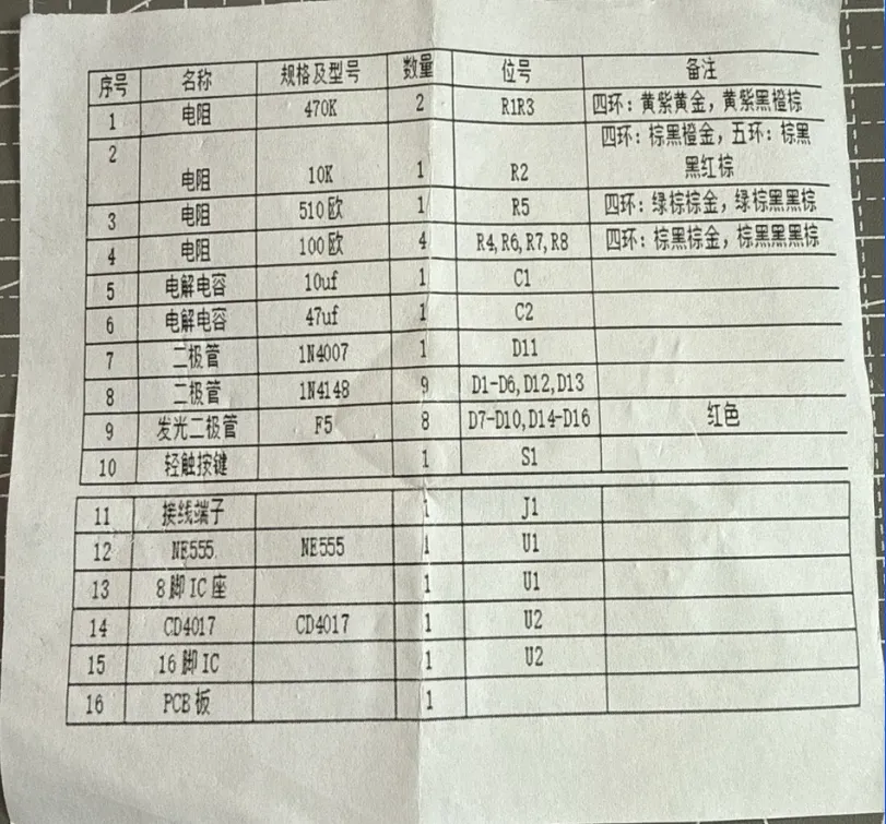
The parts list included with this YCA2109 kit specifies the specs, quantities, and PCB reference designators for the main components.
Rather than first studying the entire schematic and the principles of each chip in detail, I started with the parts list, searched for components from top to bottom, and then located their positions on the PCB. For a complete beginner like me, this approach at least let me get started.
Starting with resistors, installing them group by group
I installed the resistors first. I confirmed each resistance by reading the color bands, then found positions like R1, R2, R3 on the board. Resistors don’t require orientation, so matching the value to the position was enough.
The next components—electrolytic capacitors, diodes, and LEDs—couldn’t be placed based on position alone. The capacitors required checking polarity, the diodes required checking the band on their body, and the LED leads had to match the PCB markings. After those came transistors, a button, a terminal block, and two IC sockets.
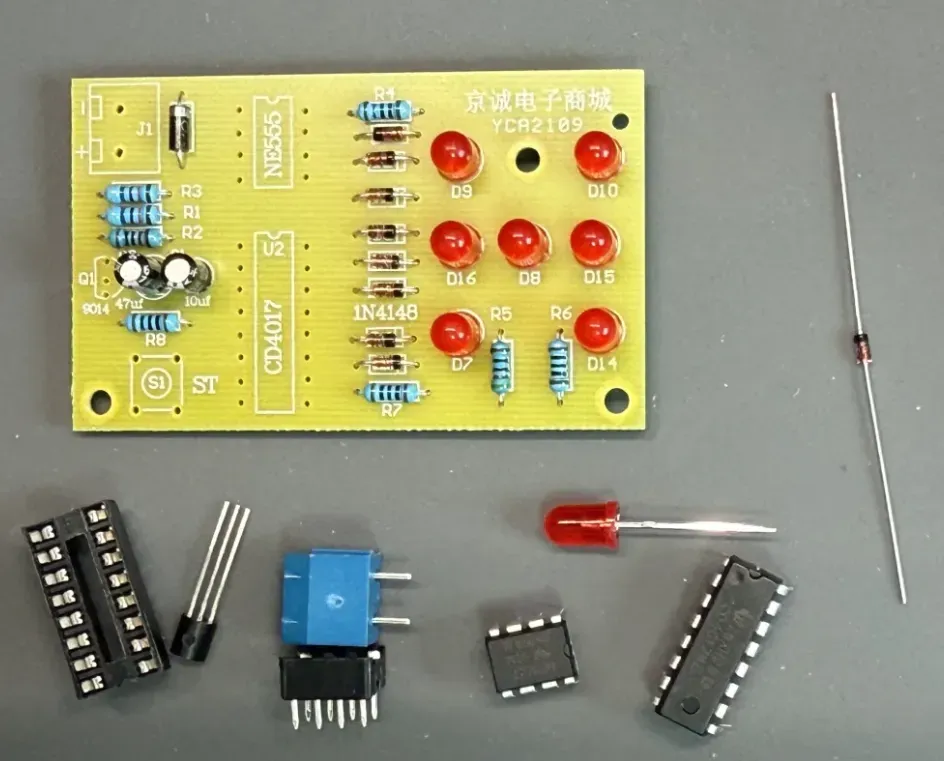
Midway through assembly, the PCB already had resistors, capacitors, diodes, and LEDs installed, with the chips, IC sockets, terminal block, and other parts waiting nearby.
After completing each group of components, I flipped the board over to solder them, then clipped the excess leads. Actually making this part took about two to three hours.
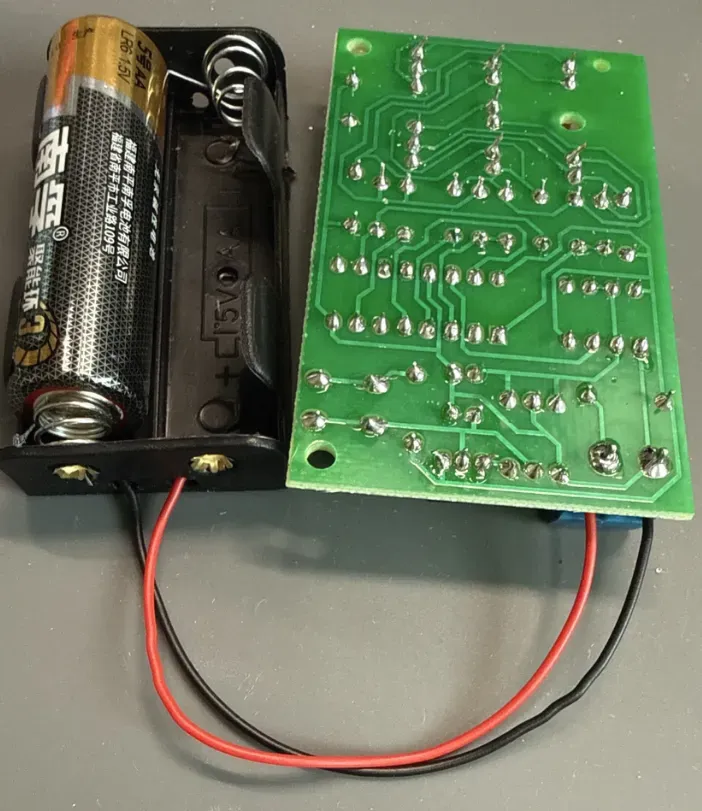
Back of the circuit board photographed during the first power-on troubleshooting, showing the through-hole component solder joints that have been soldered and lead-clipped.
This soldering session went much more smoothly than my first practice. The method that helped me the most was to first let the soldering iron tip touch both the pad and the lead, and only after both were heated, feed in the solder wire. Once I mastered that, I was no longer just chasing after the solder wire to melt it; I was proactively building a reliable connection at the joint.
It took two to three hours to assemble, and another two to three hours to troubleshoot.
After all components were soldered, I inserted the two chips, NE555P and CD4017BE, into their IC sockets, then connected the power.
As a result, not a single LED lit up, and both chips started to heat up.
The subsequent troubleshooting took about two to three more hours. I measured the voltage at the board, measured the batteries separately, replaced them with new ones, and also checked the input and the diodes. In the middle, I got meaningless readings because the multimeter dial wasn’t set properly. Only after switching to the correct diode mode did I get a result of about 0.569 V in one direction and OL in the reverse.
These actions didn’t immediately give me the final answer, but they gradually ruled out candidate issues like the battery holder and the input diode. Later, when the AI suggested I continue measuring the chip pins, I suddenly realized: I had been checking voltage and continuity, but I had never carefully confirmed whether the chips were installed in the wrong orientation.
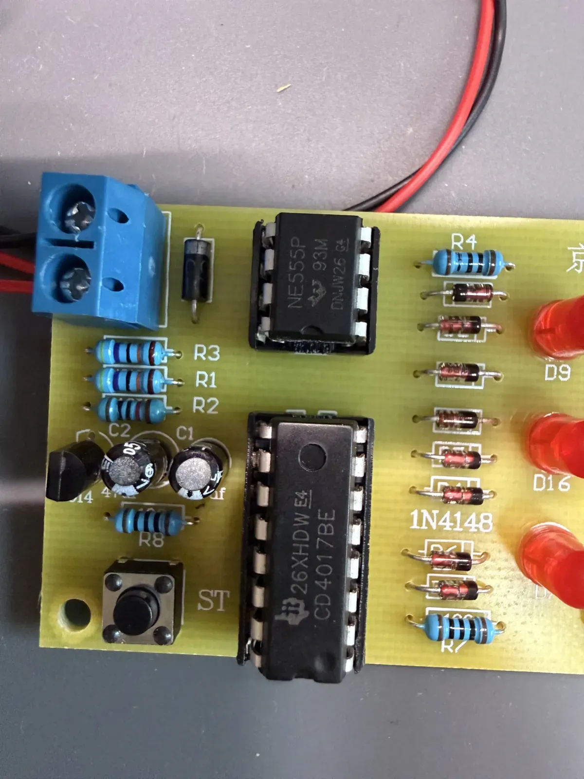
Close-up of the board front when it didn’t light up on first power-on, showing the NE555P and CD4017BE socket chips and the orientation of their notches at that time.
Matching the IC socket notch does not guarantee the chip is oriented correctly
I went back to the product page to look at the images, and found that the notch orientation of the two chips in the photos was exactly opposite to mine.
This was also the easiest thing for me to overlook this time: when installing the chips, I saw the notch on the IC socket and made the chip’s notch align with the socket’s, but I didn’t go further to confirm whether the socket itself was aligned with the orientation marking on the PCB. Completing only the first step doesn’t prove the final orientation is correct.
TI’s NE555 official datasheet and CD4017B official datasheet both give the pinout of the PDIP package in top view. During actual assembly, the orientation marking on the chip package, the pin numbers, and the orientation reference on the PCB all need to be checked together; you can’t just follow a socket that might itself have been installed backward.
After powering off, I rotated both chips by 180 degrees, powered on again, and the LEDs finally lit. Then I powered off and waited about a minute; both chips were cold, and the earlier heating did not recur.
After five or six hours, what I got was not just a board that lights up.
From starting the assembly to the final lighting, I spent about five to six hours total: two to three hours for the build itself, and another two to three hours for troubleshooting. This isn’t an exact time measurement, but it’s closer to my actual process than “it lit up as soon as I connected power after soldering.”
This electronic dice didn’t directly add any functionality to my voice assistant. It also didn’t change my ultimate direction—I still want to use AI and more highly integrated hardware to make my own small products, rather than spending a lot of time redesigning every basic circuit from scratch.
But before actually moving forward with products, I need to be able to identify components, do basic soldering, and know how to stop and check when something doesn’t work after powering on. The electronic dice filled in exactly that part of the capability.
For me, the most important thing about that first light was not proving that I had mastered hardware. It was proving that I could turn a blank board, a bag of unfamiliar components, and several hours of troubleshooting into something real that could light up.