The goal of this build was specific: use a MAX98357A audio amplifier to let an ESP32-S3 drive a small 4Ω/3W speaker. By the end, I had heard three test tones and played five web-generated voice clips in sequence.
From the moment I started working on the speaker connector to the first three tones, the process took less than half an hour, as far as I remember. The five ESP32-S3 wires were not the time-consuming part. The real delay came from a seemingly minor connector mismatch between the speaker and amplifier.
First, make the speaker connector fit
My speaker originally came with a white two-pin connector, while the MAX98357A has a green screw terminal. The white connector cannot be inserted directly into the green terminal.
At first, I bought a matching socket, hoping to use it as an adapter. When it arrived, however, I found nowhere to mount it in this build, so it did not solve the problem. I later searched for a way to remove the metal terminals from the white housing and found a much more direct approach.
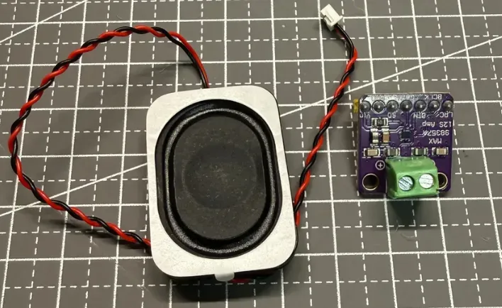
This photo records the connector arrangement on an earlier unit. The speaker specifications cannot be confirmed from the image alone, so it is not evidence for the later 4Ω/3W speaker.
Removing the terminals is straightforward, but disconnect USB and any other power source before starting:
-
Use a pointed tool to gently lift the retaining tab that holds the metal terminal inside the white plastic housing.
-
Hold the metal terminal or the wire close to the connector and pull the terminal out of the housing. Do not pull on the wire alone.
-
Loosen the screws on the amplifier’s green terminal block, then insert the two metal terminals into the speaker output positions marked
+and-. -
Tighten the screws, gently tug each wire to check for looseness, and make sure the exposed metal parts cannot touch each other.
On my speaker, the red wire connects to + and the black wire to -. That color mapping applies only to this unit; do not assume every speaker uses the same colors.
Materials and tools used this time
Materials:
-
ESP32-S3 N16R8 development board
-
MAX98357A I²S audio amplifier module
-
3525 enclosure speaker, 4Ω/3W (the description comes from the part listing; I did not independently measure its dimensions)
-
Breadboard, Dupont wires, and USB data cable
Tools:
-
Pointed tool: for lifting the retaining tab inside the white connector
-
Small screwdriver: for tightening the green terminal block on the MAX98357A
The speaker’s 3W marking is a power-handling rating; it does not mean this circuit will necessarily deliver 3W. The MAX98357A operates from 2.5V to 5.5V, and the official maximum output of 3.2W applies under specific conditions, including a 5V supply and 4Ω load. Here, VIN is connected to 3.3V, which is within the supported range, but the speaker rating is not the circuit’s actual output power.
The five wires between the MAX98357A and ESP32-S3
After connecting the amplifier to the speaker, connect the MAX98357A to the ESP32-S3. The following pin mapping worked in this build:
| MAX98357A | ESP32-S3 N16R8 | Function |
|---|---|---|
| VIN | 3V3 | Module power supply |
| GND | GND | Common ground |
| BCLK | GPIO16 | I²S bit clock |
| LRC | GPIO17 | I²S left/right channel clock, also often written as WS |
| DIN | GPIO18 | Audio data sent from the ESP32-S3 to the amplifier |
GAIN and SD are left unconnected in this build. BCLK, LRC/WS, and DIN carry the clocks and data for the I²S digital audio link. Espressif’s Arduino I²S documentation likewise describes standard-mode connections in terms of BCLK, WS, and a data pin.
I kept USB disconnected while wiring. After all five wires were in place, I checked every connection against the table again. This helped rule out incorrect power wiring, wrong GPIO pins, and loose contacts before power-up.
Do a brief power check, then upload the three-tone test
After confirming the five connections, I powered the board for about five seconds and observed it. I noticed no smoke, unusual odor, unexpected noise, or repeated restarts. This only means that no obvious problem appeared during that brief check; it does not replace longer-term temperature and stability testing.
I then uploaded a low-volume test program that played three 440 Hz tones. The speaker produced all three clearly. When I heard them for the first time, my reaction was simple: it had worked.
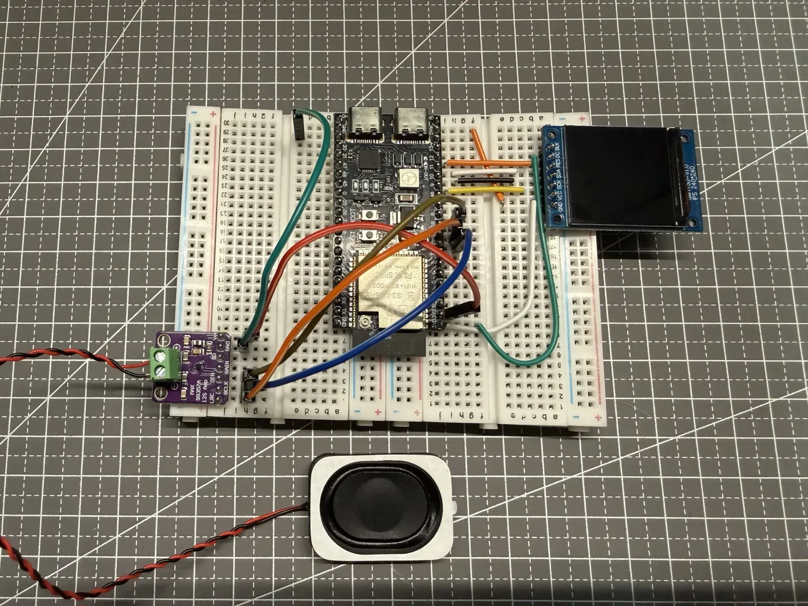
The completed physical wiring between the ESP32-S3, MAX98357A, and speaker. Use the wiring table and the labels on the actual boards for the exact pin mapping.
From three test tones to five web-generated voice clips
The three-tone test showed that the development board, amplifier, and speaker could work together. Next, I had the ESP32-S3 fetch TTS MP3 files generated by the local web app over Wi-Fi and play five voice clips in sequence. The server logs, the device’s serial output, and the audio I heard all matched.
Hearing those five web-generated clips come through the small speaker brought the joy of having actually built the thing. The earlier connector problem had finally become a working voice-output chain.
Where verification currently stands
-
Verified: physical connection between the speaker and the MAX98357A.
-
Verified: five-wire connection from the ESP32-S3 to the MAX98357A.
-
Verified: one run of the three-tone test.
-
Verified: sequential playback of five web-generated voice clips.
-
Not yet verified: microphone recording, speech recognition, AI conversation, and the complete two-way voice link.
What I completed here was “making it speak,” not a complete voice conversation. Next, I plan to add voice input so the device can hear what I say.
Technical documentation
-
Analog Devices: MAX98357A/MAX98357B datasheet — used to verify the supply-voltage range, I²S input, output-power conditions with a 4Ω load, and the bridged output configuration with the speaker connected between OUTP and OUTN.
-
Espressif: Arduino ESP32 I²S documentation — used to verify the basic roles of BCLK, WS/LRC, and the data line.
-
Adafruit: MAX98357 I²S amplifier pinouts — used as a cross-check for the bridged speaker output and pin functions on a reference module built around the same chip. It is not the board manual for the module used in this build.