PROJECT 001
AI HardwareESP32-S3 AI Voice Conversation Prototype
Building a button-triggered AI voice conversation prototype that records the user's voice, sends it to a server for language-model processing, and plays the spoken response through the device's speaker.
Built by Qihao
PROJECT OVERVIEW
Project overview
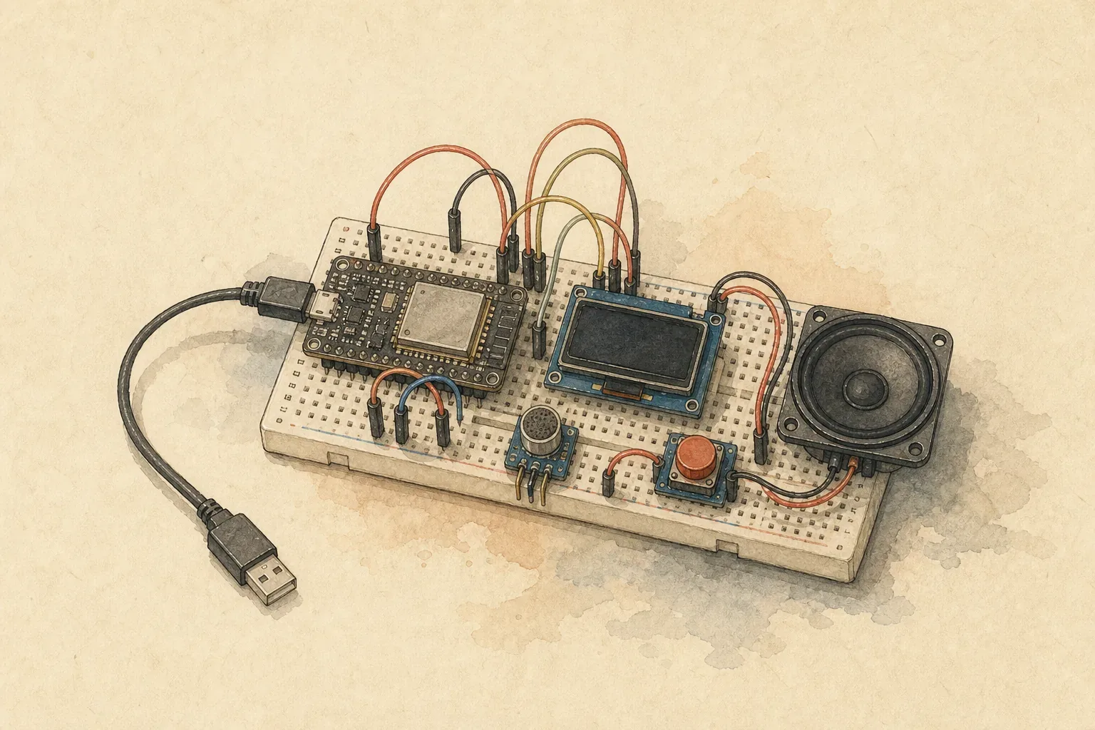
I want to turn an on-screen AI voice conversation into a physical prototype people can actually operate. It is not a complete robot yet. The first stage is to verify the smallest end-to-end interaction loop: a person presses a button and speaks, the device sends the audio to a server for processing, and the speaker plays the response.
Final interaction flow
- Press the button.
- The device starts recording.
- The recording is uploaded to the server.
- The server calls a large language model to process the conversation.
- The server returns the voice content to be played.
- The device plays the answer through the speaker.
Current progress
The project is still in progress, and overall progress remains at 35%. The button, display, and audio output chain are connected. The new pre-soldered INMP441 has also passed raw I²S capture verification, but button-triggered recording has not yet produced usable audio with the correct duration.
I connected the 4Ω/3W enclosure speaker to the MAX98357A, then connected the amplifier to the ESP32-S3 with five wires: VIN → 3V3, GND → GND, BCLK → GPIO16, LRC → GPIO17, and DIN → GPIO18.
During a brief power-on check, I observed no obvious problems. A low-volume test program then produced three tones as expected. After that, the device used Wi-Fi to play five web-generated voice clips in sequence. These results show that the current output chain works, but only as a single recorded verification run in this specific setup.
The dynamic browser-to-speaker pipeline, the end-to-end evidence from five tasks, and the current limitations are documented in “Type Text in a Browser, Hear It from an ESP32 Speaker: Testing a Local TTS Playback Pipeline”.
On the platform side, reusable MP3 files and individual device playbacks are now separate objects. The same text and generation configuration can reuse an existing audio asset, while every send still creates an independent playback job and event record. This reduces repeated TTS cost and waiting time without losing each device action. The data model, cache key, and legacy-data migration are documented in “Why the Same Text Shouldn’t Generate Another MP3: Separating Audio Assets from Playback Jobs”.
The new pre-soldered INMP441 is connected as SCK → GPIO4, WS → GPIO5, SD → GPIO6, and L/R → GND. Gate 1 verified that 16 kHz left-channel I²S data changes with sound and remains reproducible after a hard reset. The GPIO8 button also completed 10 press-and-release regression cycles. Gate 2 can end a recording and export complete data, but a 3.304-second operation captured only 5,120 samples—about 0.320 seconds at 16 kHz. This shows that display transfers are still blocking capture, so Gate 2 has not passed.
The next step is to move I²S capture into a separate task and retest it on the device. I first need a recording with the correct duration that can be played back, then I can continue with upload, speech recognition, and server-side conversation processing. At this point, the device can speak and capture raw microphone data, but it cannot yet hold a complete two-way voice conversation. I will keep updating this page as the physical build progresses, so it records the current prototype—not a final design or solution.
Issues encountered so far
When I first prepared to connect the microphone and speaker, I discovered that unsoldered pin headers and incompatible connectors could make a hardware list that looked complete on paper unusable in the real build. I recorded that experience in “AI Gave Me a Shopping List, but I Spent a Day Buying Components”.
The speaker’s white two-pin connector could not plug directly into the MAX98357A’s green screw terminal. I had bought a matching socket, but there was nowhere to use it in this assembly. I eventually removed the metal terminals from the white housing and secured them in the amplifier’s terminal block. The complete wiring process, three-tone test, and five web-generated voice clips are documented in “ESP32-S3 + MAX98357A Wiring: Play Voice Through a 4Ω/3W Speaker”.
After I connected the ST7735 display, fixed colored lines appeared along the right and bottom edges. By leaving the wiring and drawing code unchanged and switching only the panel initialization parameters, I confirmed that this screen needs INITR_GREENTAB. The full troubleshooting process is in “Color Streaks Appear on the Edges of the ST7735 Screen”.
The GMT130-V1.0 ST7789 display I connected earlier had a backlight but no pixel image, and I once thought it was damaged. Later, I kept the original pins, ST7789 driver, and 240×240 resolution, switched to an ESP32 hardware SPI path that actually applied SPI_MODE3, and set the clock to 1 MHz. The screen completed a five-color cycle and passed a power-cycle retest. The full investigation is in “ST7789 Has Backlight but No Picture: GMT130-V1.0 Lights Up After Changing from SPI_MODE0 to MODE3”.
To make the GMT130 wiring easier to understand, I worked through the roles of all seven pins and changed the wiring to SCK → GPIO9, SDA → GPIO10, RES → GPIO11, and DC → GPIO12, with VCC and BLK connected to 3V3 and GND connected to GND. Learning the underlying concepts took about two days; rewiring took five minutes. After power-up, the display still cycled through the colors correctly. I explain how those seven wires work together in “ESP32 + ST7789 Display: What Do the 7 Wires Do?”.
When preparing to connect the INMP441, I skipped the practice board and went straight into the first soldering job of my life. The six joints came out in inconsistent shapes, and I still need to determine whether the module will work reliably. The full process is in “I Understood the Tutorial, but My First Soldering Still Became a Blob”.
These problems did not stop the project. Instead, they gradually broke the vague goal of “building a voice robot” into concrete tasks I could connect, test, and verify one at a time.
STEP BY STEP
Build steps
- 01
Connect the button and display
Connect the button and ST7735 display, then verify the input trigger and screen output; this part is complete.
- 02
Connect the recording module
The new pre-soldered INMP441 is connected and has passed raw I²S capture verification. Button-triggered recording is still severely undersampled because display transfers block capture, so it has not yet produced usable audio.
- 03
Upload recordings to the server
Upload audio captured by the device to the server, establishing a stable data path for speech recognition and conversation processing.
- 04
Process conversation and generate speech
Have the server process the conversation with a large language model, generate a spoken response, and return audio the device can play.
- 05
Connect the amplifier and speaker
The MAX98357A is connected to the ESP32-S3 with five wires and has driven a 4Ω/3W enclosure speaker through three test tones and five web-generated voice clips; only the output chain has been verified so far.
BILL OF MATERIALS
Materials and tools
| Part | Model | Quantity | Purpose |
|---|---|---|---|
| Development Board | ESP32-S3 | 1 | Controls button, screen, recording, and voice playback flow |
| TFT Display | 1.8-inch 128×160 ST7735 | 1 | Displays device status and interaction feedback |
| Button | — | 1 | Triggers recording |
| Digital Microphone | INMP441 | 1 | Captures recording |
| I2S Digital Amplifier | MAX98357A | 1 | Drives speaker to play voice |
| Enclosure speaker | 3525, 4Ω/3W | 1 | Plays the voice content returned by the server |
Tools needed
- Breadboard
- Dupont wires
- Soldering iron and solder wire
- Pointed terminal-release tool
- Small screwdriver
MAKING OF
Build logs
Follow the project from its initial idea through experiments and its current state.
The tutorial made sense, but my first solder joint still ended up as a blob.
For my first time soldering pins onto an INMP441, I skipped the practice board and went straight to the real thing. Twenty minutes later, I had six oddly shaped solder joints. This failure taught me: tutorials and AI can teach knowledge, but hands-on skill only grows from practice.
ST7789 Backlight but No Image: GMT130-V1.0 Works After Switching from SPI_MODE0 to MODE3
A GMT130-V1.0 had a working backlight but never displayed a single pixel, even though the driver chip and resolution were correct. This article retraces how I moved from a black screen on software SPI Mode 0 to hardware SPI that actually applies SPI_MODE3, then verified the fix with a five-color loop and a power-cycle test.
ESP32-S3 + MAX98357A Wiring: Play Voice Through a 4Ω/3W Speaker
A hands-on ESP32-S3 voice playback build: adapt a two-pin speaker connector to the MAX98357A screw terminal, complete the five-wire I²S connection, and verify the audio output with three test tones and five web-generated voice clips.
Type Text in a Browser, Hear It from an ESP32 Speaker: Testing a Local TTS Playback Pipeline
I moved the ESP32-S3 from playing audio embedded in firmware to speaking text entered dynamically in a browser. This article documents the working path from the web UI through local TTS and a task queue to the ESP32, MAX98357A, and speaker—and clearly marks the voice-input work that remains.