
If the main image on an ST7735 looks normal but fixed, continuous thin colored lines appear on the right or bottom, don’t rush to conclude that the screen is damaged. Keep the wiring and drawing code unchanged, and first check the panel initialization type and address offset in initR().
The issue isn’t that it fails to display entirely — it’s that the edges aren’t being covered correctly.
In the ESP32-S3 AI voice dialogue prototype I’m building, I swapped in a 1.8-inch, 128×160 ST7735 screen.
But looking closely, there are still very thin colored artifact lines on the right and bottom of the image. They are concentrated at the edges, continuous and fixed in shape, not randomly scattered across the whole screen.
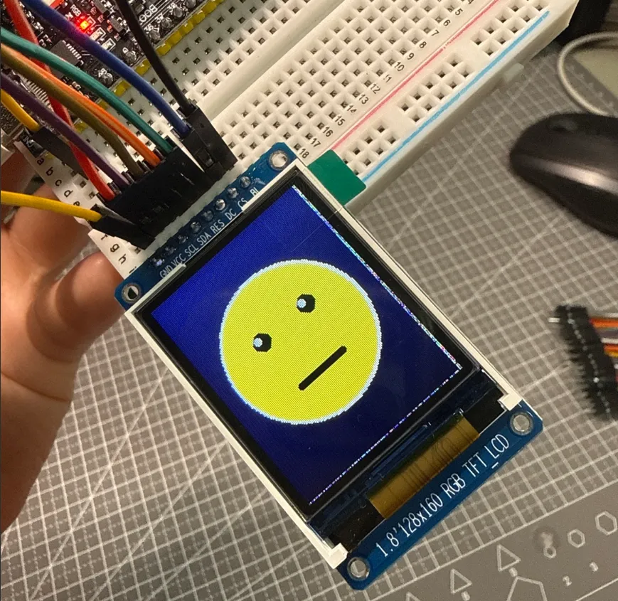
Photo of the ST7735 before the fix: the main facial expression is already displayed, but thin colored lines are still visible along the right and bottom edges.
When I saw the anomaly, I initially still suspected the screen itself was faulty. The turning point came from a comment I received after publicly documenting my learning process: someone reminded me to check whether the image had an ‘offset.’ That keyword reframed the question from ‘is the screen broken?’ to a more specific one — are the coordinates written by the program aligned with the actual visible area of this panel?
First confirm the screen, then discuss the initialization parameters.
The back of this module clearly labels DRIVER IC: ST7735, and the front is specified as 1.8 inches, 128×160, with an SPI interface. The resolution here only indicates the visible area size; it alone cannot determine which initR() parameter should be chosen.
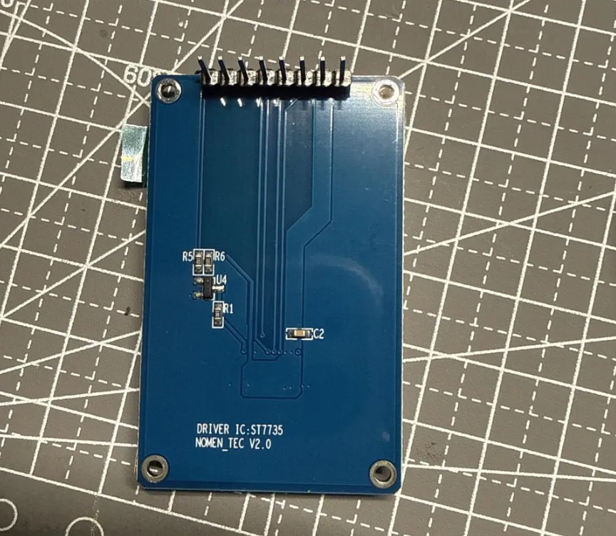
Photo of the back of the screen module and pin headers, showing the DRIVER IC: ST7735 label and the module version silkscreen.
Adafruit’s ST7735 library offers options such as INITR_BLACKTAB, INITR_GREENTAB, and INITR_REDTAB. These are not merely ‘theme colors’ — they are initialization paths prepared for different ST7735 panel configurations. The official examples also explicitly distinguish between ordinary 1.8-inch screens and 1.8-inch screens that have an offset:Adafruit graphicstest 1.11.0 example.
Test environment and recording limitations for this session
- Control board: ESP32-S3;
- Display module: labeled on the back
DRIVER IC: ST77351.8-inch 128×160 SPI module; - Display orientation:
setRotation(0); - Only modification:
initR()fromINITR_BLACKTABswitched toINITR_GREENTAB; - Retest method: after re-uploading, observe all four edges, then power-cycle and retest.
At the time, I did not save the exact version number of the Adafruit ST7735 library, so this article cannot prove that all library versions will produce the same result. Below, I pin the explanatory source code to upstream 1.11.0, solely to illustrate the initialization and offset mechanism; it does not mean that this was the version used at the time. To reproduce the experiment strictly, first record the version in the Arduino Library Manager or lock the corresponding commit, then run the same single-variable test.
The key difference between BLACKTAB and GREENTAB is the starting offset
Continuing to look at Adafruit_ST7735.cpp: INITR_GREENTAB sets the column start to 2 and the row start to 1; other paths keep the default zero offset without extra settings. Then setRotation() uses these start points for display coordinate mapping in the current orientation. The corresponding implementation can be seen at Adafruit_ST7735 1.11.0 source.
// INITR_GREENTAB
_colstart = 2;
_rowstart = 1;

// Other paths without separately set offsets
// colstart, rowstart remain at the default 0
Think of it this way: the logical coordinate (0, 0) in the program does not necessarily correspond exactly to the first pixel of the visible area of the LCD panel. Different modules, even if both labeled ST7735, 128×160, may need different row and column start points because the mapping between the panel and the controller’s framebuffer differs.
If the initialization parameters use start points that do not fit the current panel, the main content may still appear normally, but the entire image will be slightly shifted relative to the visible area, and the edges may leave narrow strips that were not correctly covered by this drawing.
Verify with a single-variable experiment rather than rewiring all lines at once.
The program at that time used:
tft.initR(INITR_BLACKTAB);
tft.setRotation(0);
To make the results meaningful, I kept all of the following unchanged:
-
The wiring between the screen and the ESP32-S3;
-
128×160 resolution and portrait orientation;
-
Coordinates and colors for drawing a normal face;
-
Button logic and other program structure.
The only modification was:
tft.initR(INITR_GREENTAB);
tft.setRotation(0);
After re-uploading, the colored lines on the right and bottom disappeared completely, and the colors, orientation, and screen position were all normal. I then powered off and restarted, and the screen still displayed correctly. This indicates that under the documented hardware, orientation, and program conditions, INITR_GREENTAB is the correct initialization configuration for this panel.
In the future, when encountering similar issues, I will troubleshoot in this order:
-
First confirm the driver chip, visible resolution, and actual interface, rather than relying only on the product title.
-
On first power-up, display a full-screen solid color or draw a test pattern covering all four edges to check colors, orientation, position, and edge completeness.
-
If the main image is stable and the anomaly is just a fixed, continuous narrow band at an edge, prioritize checking the initialization type and row/column offset.
-
Switch only one of the BLACKTAB, GREENTAB, or REDTAB options at a time; do not change wiring, SPI pins, and drawing coordinates simultaneously.
-
After finding the correct configuration, power-cycle and retest, then record it as the hardware configuration for this specific module.
The value of this sequence is that each modification can answer a specific question. If random noise, flickering, or whole-screen instability appears inside the image, you should also return to power supply, connections, SPI speed, and signal integrity for further troubleshooting; not all display anomalies can be attributed to offset.
Public learning turns ‘not knowing how to ask’ into a verifiable problem.
The biggest takeaway from this troubleshooting was that the process of public learning quickly drew comments from professionals and helped find the problem. Initially I thought the screen was broken, but when someone in the comments told me to check for an offset, I realized how to continue communicating with AI.
What really worked this time was not a direct answer, but a more accurate observational perspective. The comment section provided the keyword ‘offset’; I then gave the AI the specific screen model, the fixed edge colored lines, and the initialization code, and the problem turned from a vague guess into an experiment where I could check the source, change one line of code, re-upload, and power-cycle to retest.
For me, public learning is not about showing results only after everything is correct. Clearly describing real phenomena, failure photos, and steps already tried increases the chance of receiving useful feedback. Combining professionals’ experience, AI’s retrieval and synthesis capabilities, and my own hands-on single-variable verification makes troubleshooting much faster.
Applicability boundaries
The conclusions in this article have been verified on this current 1.8-inch 128×160 ST7735 module with power-cycle retesting, but they are not a universal answer for all ST7735 modules. Different manufacturers, batches, and panel combinations may require BLACKTAB, GREENTAB, REDTAB, or other dedicated configurations. The correct approach remains to first verify documentation, then use a test pattern covering all four edges for single-variable verification.