When I first powered up this screen, I simply followed the wiring table the AI gave me: whichever wire goes to which GPIO, I just connected it. But when I wanted to reorganize the messy wiring, I realized I didn’t dare unplug even a single wire.
The problem wasn’t that I couldn’t plug wires into a breadboard—it was that I didn’t know why these seven wires had to be connected this way. I couldn’t explain which ones handle power, which ones carry the image, which positions can be adjusted, and which ones can’t be swapped casually.
From deciding to understand the seven wires to finally completing the rewiring, it took me about two days. The actual hands-on rewiring only took five minutes.
**Who this article is for:** People who are connecting an ST7789 screen to an ESP32 for the first time, can follow a wiring table, but don’t know why each wire is connected the way it is.
**What you’ll get from reading it:** A way to fit the seven wires into a complete display chain, and an understanding of which constraints must be preserved when re-planning the wiring.
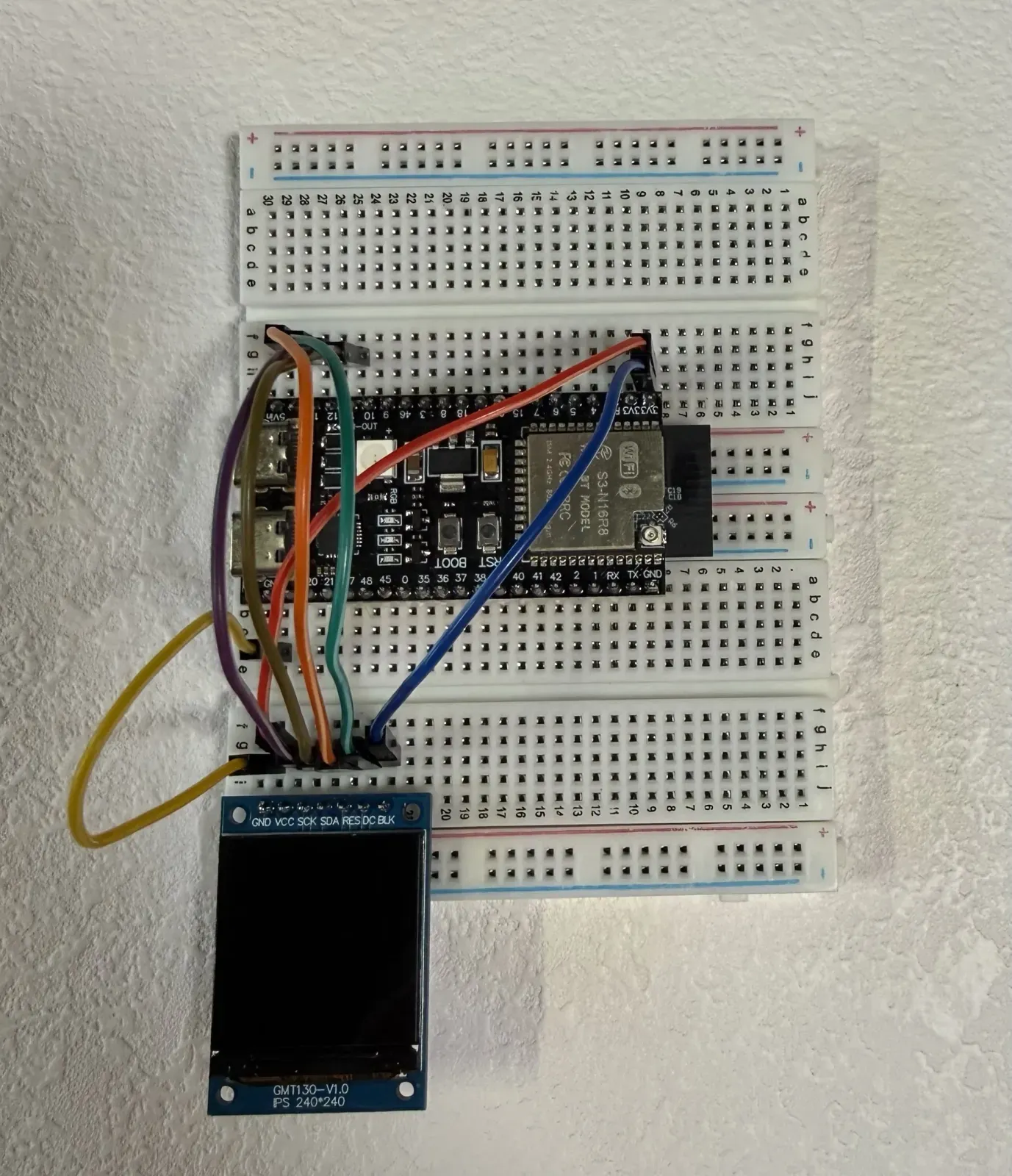
Before rewiring, the GMT130 screen and ESP32-S3 were connected with several longer wires, with the lines crossing above the breadboard.
Don’t memorize the seven English names yet: they actually only do four kinds of jobs
I’m using the GMT130-V1.0. The controller marked on the back of the screen is the ST7789, and the interface is SPI. The pin header has seven names in total: GND, VCC, SCK, SDA, RES, DC, BLK.
If you try to memorize the abbreviations one by one at the start, it’s easy to get more confused the further you go. Instead, classify them by job type first—the seven wires actually only do four kinds of things:
| Job category | Pins | One sentence to remember first |
|---|---|---|
| Power and reference | VCC、GND | Provides the module with electrical power, and makes the ESP32 and the screen share the same voltage reference point. |
| Backlight | BLK | Turn on the light source behind the LCD. |
| Reset | RES | Bring the ST7789 back to a point where it can be re-initialized. |
| SPI write | SCK, SDA, DC | Write commands, parameters, and pixel data from the ESP32 into the screen. |
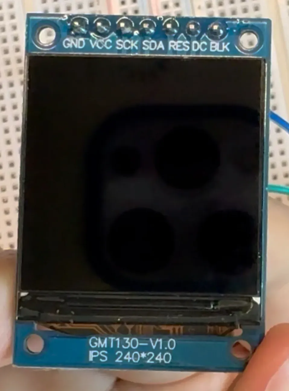
On the front of the GMT130-V1.0, the pin headers are labeled in order: GND, VCC, SCK, SDA, RES, DC, BLK.
This classification table is the map for understanding all the details that follow. For any wire, first ask which category it belongs to, then ask what it does within that category.
How the seven wires come together to form an image
These four categories of work are not executed by the seven wires in a sequential queue, but rather by several branches working together simultaneously.
-
**VCC and GND establish the working foundation.** The screen module gets power, and the ESP32 and screen also share a common voltage reference.
-
**BLK enables the backlight branch.** It only provides light; it is not responsible for generating pixels.
-
**RES returns the controller to a known starting point.** After reset, the program must still continue sending initialization commands.
-
**SCK, SDA, and DC perform the SPI write.** The ESP32 sends initialization commands, parameters, and pixel data to the ST7789.
-
**The ST7789 drives the LCD pixels.** The backlight passes through the controlled red, green, and blue subpixels, and only then does the human eye see the colors the program requested.
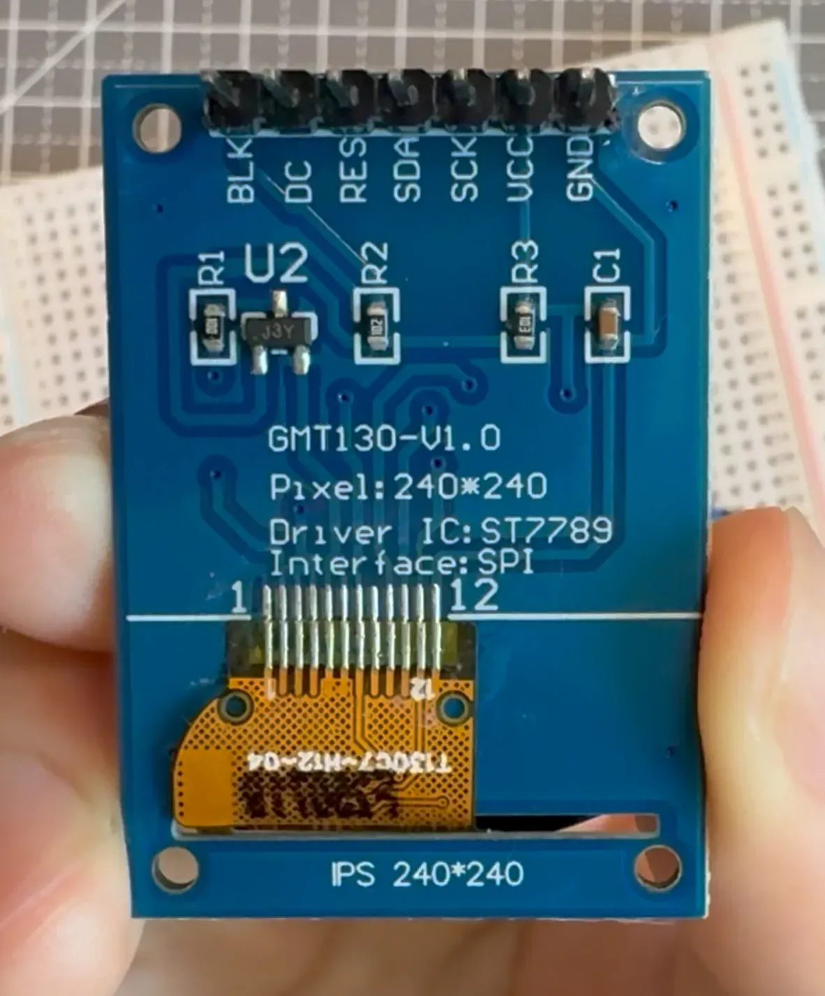
The back of the GMT130-V1.0 is labeled 240×240, Driver IC ST7789, and Interface SPI.
**The backlight being on and successful pixel writing are two separate things.** The screen lighting up only indicates that the backlight and part of the power supply path are working; it does not prove that reset, initialization, SPI communication, and pixel writing have all succeeded.
VCC and GND: not only must there be power, but also a shared zero point.
VCC supplies power to the module. In my actual GMT130-V1.0 and ESP32-S3 hardware, VCC is connected to 3V3 on the dev board. This conclusion only covers the module I have verified; it does not mean that all similarly appearing screens can be directly copied without checking the specifications, nor should you change the connection to 5V based on this.
GND has two easily confused roles.
-
It provides the current return path, allowing the power supply loop to be closed.
-
It lets the ESP32 and the screen share the same voltage reference, that is, a common “zero point.”
When the screen judges whether SDA is 0 or 1, it is not recognizing a number that travels along the wire; instead, it is comparing the voltage on SDA with the screen’s GND. When the two sides do not share a common ground, the high and low levels seen by the screen have no reliable common reference.
Therefore, saying “VCC supplies power and GND handles the loop” is not complete enough. A more accurate statement is:VCC provides electrical energy, while GND provides both the return path and the common reference.
BLK and RES: one controls light, the other restarts the controller.
**BLK is the backlight control.** I connected BLK directly to 3V3, so the backlight stays on after power-up. However, the backlight is only the light source behind the LCD; it does not send commands, and it cannot create red pixels out of nowhere.
**RES is the hardware reset.** Through RES, the ESP32 sends a reset signal to the ST7789, returning the controller to its specified initial state. What it addresses is “restarting from a known starting point,” not “automatically turning the screen black or red.”
After the reset, the program still needs to send initialization commands and write pixel data into the display memory. Also, precisely because BLK and RES are on separate branches, when RES is pulled, the backlight connected directly to 3V3 remains on.
SPI write: SDA provides the content, SCK provides the timing, and DC provides the type.
SPI can first be understood as a transmission convention that both sides follow. It is not a phrase in “Chinese” or “English,” but a set of rules covering who sends data, how high and low levels are represented on the wire, when to sample, and in what order the data is organized.
This seven-pin screen does not bring out the read-return line or the chip-select line. In this article, the three lines that matter most are SCK, SDA, and DC:
| Pin | What it does | What actually happens |
|---|---|---|
| SDA | Content | The ESP32 sets each bit being sent, one after another, to either high or low level. |
| SCK | Read timing | When the clock edge arrives, the ST7789 records the current stable value on SDA. |
| DC | Content type | Low level indicates a command; high level indicates parameters or pixel data. |
What is an “edge”? When a wire changes from low to high, that moment is called a rising edge; when it changes from high to low, it is a falling edge. In the Mode 3 configuration I verified successfully, the ESP32 first lets SDA settle, then makes SCK produce the agreed rising edge, and the ST7789 records whether SDA is 0 or 1 at that moment.
The easiest point to misunderstand here is: **the screen does not automatically read just because SDA changes by itself.** Even if SDA stays high the entire time, as long as SCK provides two consecutive read moments, the screen can still record two 1s.
DC acts like a byte’s category marker. If the ESP32 originally intended to send a command, but DC is erroneously held high the entire time, even if SDA and SCK are both normal, the ST7789 will treat the received eight bits as data, not as a command.
SPI is also not “can only send one byte at a time, and it’s over after sending.” Software often organizes consecutive bits into bytes every eight bits, but a single drawing operation will continuously send many commands, parameters, and pixel bytes.
Taking RGB565 as an example, one pixel requires 16 bits, which is 2 bytes. A full 240×240 screen has a total of 57,600 pixels, and the pixel content alone is 115,200 bytes. Therefore, SPI clock speed and software overhead do affect the speed of changing the entire screen’s color.
How one line of fillScreen eventually turns the screen red
Now let’s put the seven wires back into a real call. When the program executes tft.fillScreen(red) , roughly the following steps happen behind the scenes:
-
The display library converts “fill the entire screen” into a 240×240 drawing area.
-
The program first sends commands for column address, row address, and start writing to display memory.
-
DC lets the ST7789 know whether what it currently receives is a command, or command parameters and pixels.
-
SDA gives the high or low level for each bit in sequence, and SCK provides the read rhythm.
-
The ST7789 writes the continuously received RGB565 colors into display memory and drives the corresponding sub-pixels on the LCD panel.
-
The BLK branch has already turned on the backlight. The backlight passes through the LCD, and the human eye finally sees the entire block of red.
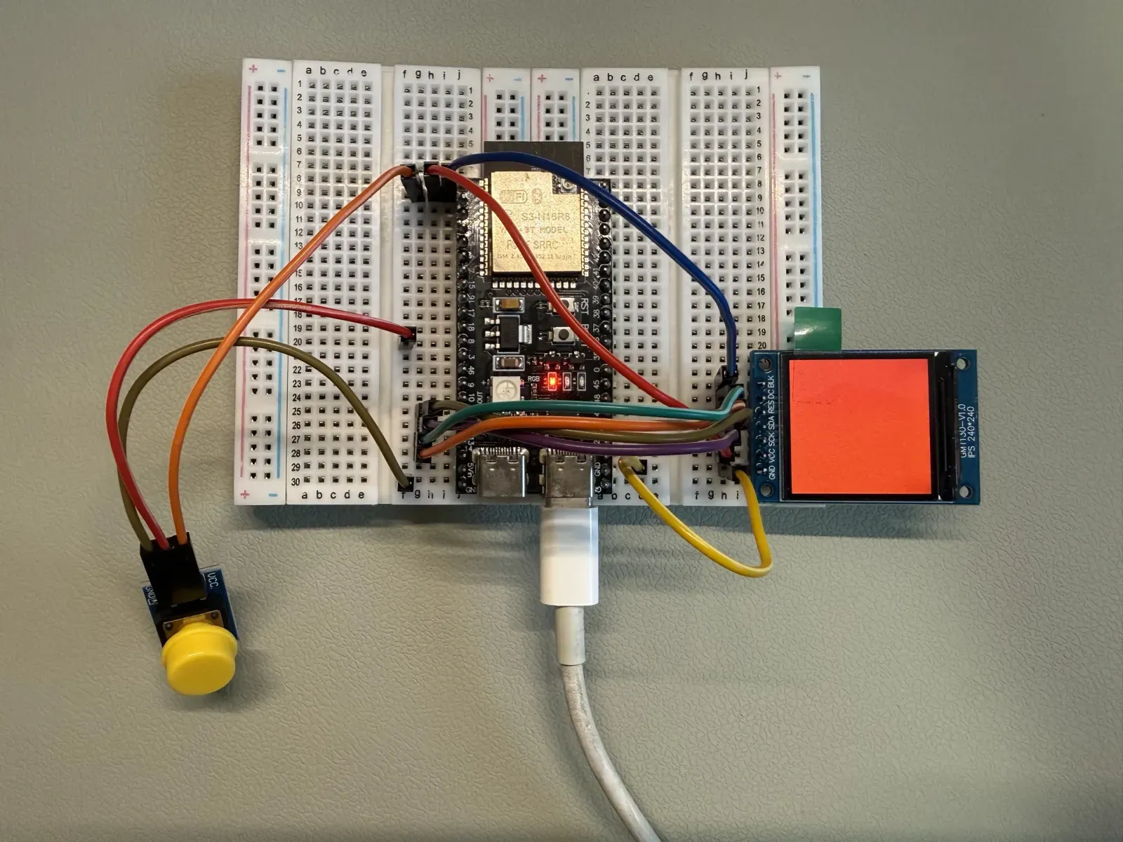
The ESP32-S3 uses hardware SPI Mode 3 to drive the same GMT130-V1.0, and the screen displays a solid red image.
This chain also explains why, when troubleshooting, you cannot just ask “is the screen lit or not.” More useful questions are: Is power and a common reference established? Is the backlight enabled? Is the controller reset and initialized? Are the SPI commands and pixels actually written?
Mode 3 is the condition already verified for my GMT130-V1.0, the current library version, and the program; it does not mean all ST7789 screens must use Mode 3. For other modules, you should still first check the specific documentation and then perform single-variable tests.
After understanding this, how to re-plan the wiring
After understanding the seven wires, “autonomous routing” is no longer about randomly plugging into seven holes, but first determining which constraints must be preserved.
-
**Only change the path the wires take, not the signal endpoints:** This is physical cable management and generally does not require code changes.
-
**Move SCK, SDA, RES, and DC to other suitable GPIOs:** This is a pin modification. After moving the wires, the GPIO definitions in the code must also be changed accordingly, and you must check whether the new GPIOs are occupied by other hardware.
-
**VCC and GND:** They are not ordinary GPIOs that can be arbitrarily replaced. The supply voltage, common ground, and module electrical limits must be preserved.
The current interface I confirmed after re-wiring is as follows:
| GMT130/ST7789 | ESP32-S3 | Category |
|---|---|---|
| GND | GND | Loop and common reference |
| VCC | 3V3 | Module power supply |
| SCK | GPIO9 | SPI clock |
| SDA | GPIO10 | SPI data write |
| RES | GPIO11 | Controller reset |
| DC | GPIO12 | Command/data select |
| BLK | 3V3 | Backlight always on |
When rerouting, I adjusted the start, end, and path of the seven wires and replaced the original stranded wires with breadboard-specific wiring. After repowering, the screen still changes colors as it did with the original wiring.
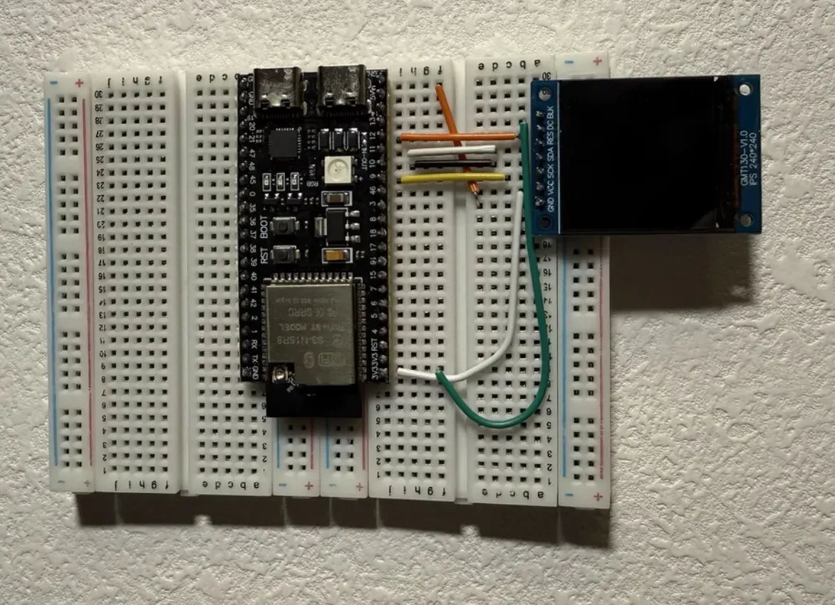
After rewiring, I switched to shorter breadboard-specific jumper wires between the GMT130 and the ESP32-S3, with the routing kept close to the breadboard layout.
What really changed over these two days is not a new screen feature. The screen still just cycles through colors. The real progress is that I began to understand the basics behind these pins and can now plan the wiring more easily on my own.
The actual wiring took only five minutes, but the previous two days were not wasted. Because next time I run into a similar problem, I won’t just stare at a wiring table and copy it blindly. I can first identify power, reference, control, and data, then decide which endpoints are fixed and which signals can be reassigned after changing the code accordingly.
Finally, I use these five questions to check my wiring.
-
Have I confirmed the screen’s exact model, controller, interface, and allowed voltage?
-
Which category does each of VCC, GND, BLK, RES, SCK, SDA, and DC belong to?
-
Are the ESP32 and the screen sharing a common ground, and is the power supply using the already-confirmed voltage?
-
If I changed the GPIO for SCK, SDA, RES, or DC, was the code updated accordingly?
-
After power-up, can I distinguish between ‘backlight is on’ and ‘pixels are actually written successfully’?
When I can answer all five questions, the seven wires are no longer a wiring table to copy blindly, but a display chain I can explain, plan, and check on my own.
Sources and Scope of Applicability
The specific GPIOs, 3.3 V power supply, SPI Mode 3, and display results in this article cover only the GMT130-V1.0, ESP32-S3 N16R8 development board, and corresponding software environment that I actually used and verified. Different screen modules, even if they also use ST7789, should be checked against their own module documentation first.