This 1.3-inch display had a faint backlight. The ESP32-S3 ran normally, and the serial monitor kept logging each screen change, but not a single pixel appeared. After troubleshooting for a while, I concluded that the display was broken, swapped in an ST7735, and continued the project.
Later, someone with relevant experience on social media suggested that I first confirm the exact display version and driver configuration. That advice reframed the problem from “Is the display broken?” to a more precise question: do the driver chip, resolution, interface, and SPI mode all match?
“The screen does not light up” does not always mean it is broken
I initially described the problem as “the screen does not light up.” On closer inspection, however, the backlight had a faint glow; only the pixel image was missing. Those are two different symptoms:
-
No backlight:First check VCC, GND, BLK, and power supply.
-
Backlight present, no pixels:Backlight power doesn’t mean the display controller has correctly received initialization commands and pixel data; continue to check reset, wiring, driver, and SPI communication.
In my environment, the serial logs and button switching work fine, but that only proves the ESP32 is running the program, not that the screen actually receives recognizable SPI data. This is also the most common illusion during troubleshooting: the program is running, but that doesn’t mean the display link is established.
Driver chip matching doesn’t mean all communication configurations match.
The model on the back of the screen is GMT130-V1.0. The physical silkscreen and the manufacturer’s product information point to the same set of details: 1.3 inch, 240×240, ST7789, SPI interface. The manufacturer’s page also lists it as a 4-wire SPI module:GMT130-V1.0 manufacturer product page.
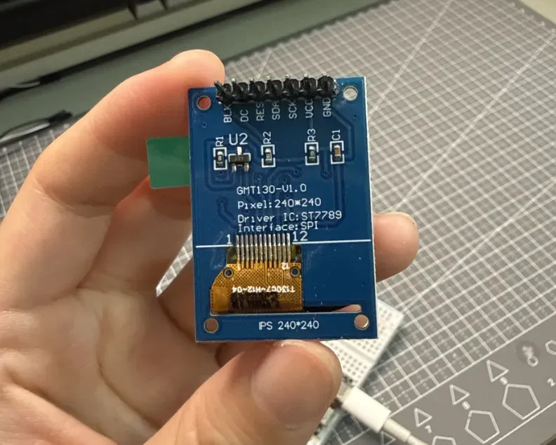
The GMT130-V1.0 module back is marked with 240×240, ST7789, and SPI interface.
Therefore, the following three items in the original program actually match:
-
Using Adafruit_ST7789: matches the ST7789 driver chip.
-
Calling tft.init(240, 240, …): matches the 240×240 resolution.
-
Setting TFT_CS = -1: matches this seven-pin module without a dedicated CS pin.
What was really missed is another layer:How to send data with the timing the screen can recognize.. SPI mode determines the idle high/low level of the clock, and on which clock edge data changes and on which edge it is sampled. Espressif’s SPI documentation also lists clock, MOSI, and chip select as separate SPI bus signals, and explains that the ESP32’s SPI pins can be configured during initialization:Arduino-ESP32 SPI API.
In other words,ST7789 answers the question “which type of controller should we talk to”, SPI_MODE0 / SPI_MODE3 answers the question “how the clock and data should cooperate”. Choosing the former correctly does not automatically guarantee the latter is also correct.
The five-argument constructor made me think Mode 3 had already been tested
The original solid-color diagnostic used the five-argument constructor of Adafruit_ST7789:
Adafruit_ST7789 tft(TFT_CS, TFT_DC, TFT_MOSI, TFT_SCLK, TFT_RST);
tft.init(240, 240, SPI_MODE0);
After statically inspecting Adafruit’s official source code, I realized: this five-argument constructor selectssoftware SPI. In the Adafruit GFX 1.12.6 I installed, the software SPI branch drives SCK and MOSI itself; the SPI mode passed to the initialization function is only applied in the hardware SPI SPISettings path. The relevant implementation can be found in Adafruit_SPITFT 1.12.6 source code and Adafruit_ST7789 1.11.0 source code for verification.
This means that, with the current library version and coding style, simply replacing the SPI_MODE0 text with SPI_MODE3 does not prove that Mode 3 timing is actually generated on the pins. To verify this hypothesis, we need to switch to a hardware SPI constructor path that actually applies the SPI mode.
Keeping the wiring unchanged, create a minimal hardware SPI Mode 3 program
The new diagnostic preserves the original pin mapping:
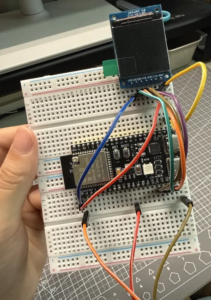
The ESP32-S3 and seven-wire GMT130-V1.0 wiring used during debugging.
The program only changes the communication path and mode, and sets the frequency to a conservative 1 MHz:
Adafruit_ST7789 tft(&SPI, TFT_CS, TFT_DC, TFT_RST);

SPI.begin(TFT_SCLK, -1, TFT_MOSI, TFT_CS);
tft.init(240, 240, SPI_MODE3);
tft.setSPISpeed(1000000);
Then, every two seconds, the program does just one thing: it fills red, green, blue, white, and black in sequence, while printing the current color to the serial port. This answers two questions at once: exactly which version of the program the ESP32 is running, and whether the screen is genuinely receiving pixel data.
Mode 0 black screen, Mode 3 lights up
Putting several actual tests together makes the comparison clear:
| Test path | Communication timing | Measured result |
|---|---|---|
| Early hardware SPI expression program | Mode 0 | Faint glow, no pixel image |
| Software SPI solid-color program | Current library path is fixed to Mode 0 form | Serial loop normal, but screen shows no pixels |
| New hardware SPI solid-color program | Actually uses SPI_MODE3, 1 MHz | Red, green, blue, white, black cycle normally |
After uploading the new program, the screen I had previously judged as damaged displayed a complete solid color for the first time.
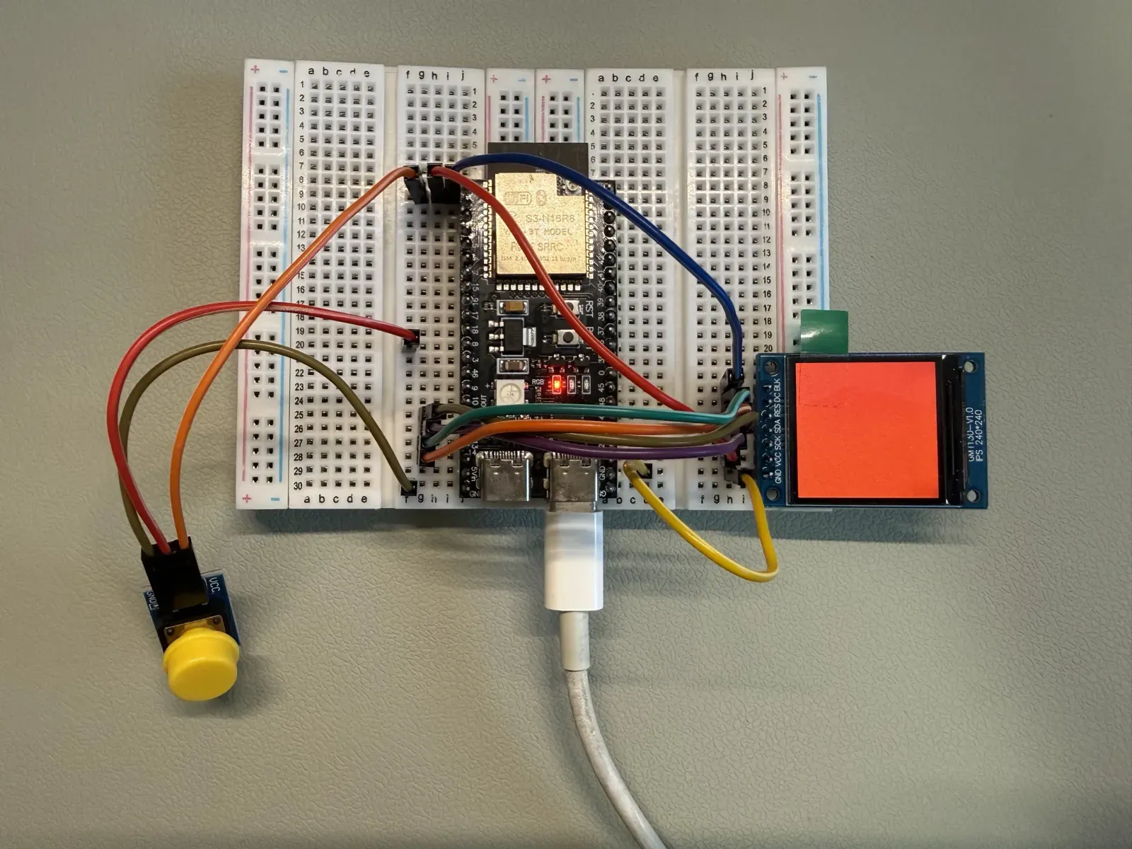
After switching to hardware SPI and setting SPI_MODE3, the GMT130-V1.0 displays a solid red screen.
Keeping the code and the seven wire connections unchanged, I unplugged the USB, confirmed the board was powered off, and then reconnected it. The screen cycled through the five colors again, and the serial port also output continuously:
DIAG MODE3 frame: RED
DIAG MODE3 frame: GREEN
DIAG MODE3 frame: BLUE
DIAG MODE3 frame: WHITE
DIAG MODE3 frame: BLACK
Therefore, this conclusion is not ‘it happened to light up once,’ but rathera power-off restart retest was completed under the current hardware, library version, pin, and wiring conditions..
If you encounter the same phenomenon, how can you narrow it down?
-
First, let’s clearly state the symptom.Distinguish among no light at all, backlight but no pixels, wrong colors, offset, or garbled screen.
-
Confirm the exact module model.Don’t guess the driver based only on “1.3 inch” or “240×240”; first check the silkscreen on the back and the manufacturer’s documentation.
-
Break down the matching items.Check separately the driver chip, resolution, interface type, CS structure, pin mapping, and SPI mode.
-
Use the serial output to confirm the program’s identity.Logs only prove that the program is running, not the screen result, but they help avoid mistaking an old program for a new test.
-
Change to a minimal solid-color program.First remove buttons, emojis, and business logic, and display only one solid color at a time.
-
Confirm whether the mode is actually applied by the library.Don’t just look at the parameter name — check whether the current constructor uses software SPI or hardware SPI.
-
Try to change only one assumption at a time.Keep wiring, pins, driver, and resolution unchanged, then compare Mode 0 with Mode 3.
-
After success, power off and test again.Only after confirming that it still recovers after a restart, elevate the conclusion from a one-time success to a verified repeat.
In the AI era, domain knowledge still determines what questions you can ask.
The reason I could return to driver and communication configuration this time is that during public learning, a netizen with professional experience reminded me to investigate this direction. Without a hardware background, I didn’t know how to describe the problem to AI, ask about the constructor and SPI mode, so I could only conclude “the screen is broken” based on “it never displays.”
Public learning allowed me to receive guidance from professionals and speed up problem-solving, but I also need to build up basic knowledge. Only when I have a basic understanding of power supply, pins, driver, and communication will I know what to observe, how to ask AI, and how to verify its suggestions the next time I encounter a problem.
This is not to say that you must become a hardware expert before using AI. A more practical approach is: while working on a project, fill in the concepts that keep blocking you. AI can quickly generate candidate answers, while domain knowledge helps me turn vague symptoms into checkable questions and decide which answer is worth powering up to verify.
Conclusion boundaries
GMT130-V1.0 specification and sample-code PDF . Technical references